
Spray Geometry and Patternation
LaVision’s SprayMaster Geometry package extracts spray plume morphology and geometry information from backlight and light sheet spray images.
Depending on the optical arrangement, the spray image obtains information about the spray pattern (radial spray cuts) or the spray plume shape and propagation (axial spray cuts).
Analysis of multi-hole injectors (e.g. automotive fuel sprays) reveals geometry information for each individual spray cone separately.
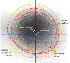
Radial spray cuts: spray patternation
Radial cuts are derived from light sheet images in cross section with the spray axis.
- Spray pattern area and its equivalent diameter
- Mass circle diameters according to SAE definition
- Centroid position based on spray image intensity
- Largest and shortest radius of the pattern rim
- Plots about radial and angular spray distribution to reveal the structural characteristics of spray plumes
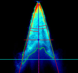
Axial spray cuts: plume geometry and propagation
Axial cuts are aligned with the spray propagation direction. Measurements are achieved using light sheets, global lighting or backlighting.
- Spray cone angle measured e.g. at a given distance from the orifice
- Bent angle (deviation from orifice axis) and both
- Half angles to indicate the symmetry and direction of the spray plume
- Tip penetration to represent the propagation of the spray
- Angular spray density plot to show the uniformity of the spray
Need Inquire ?
If you need more information or quotation about this product, Our sales representative will reply as soon as possible